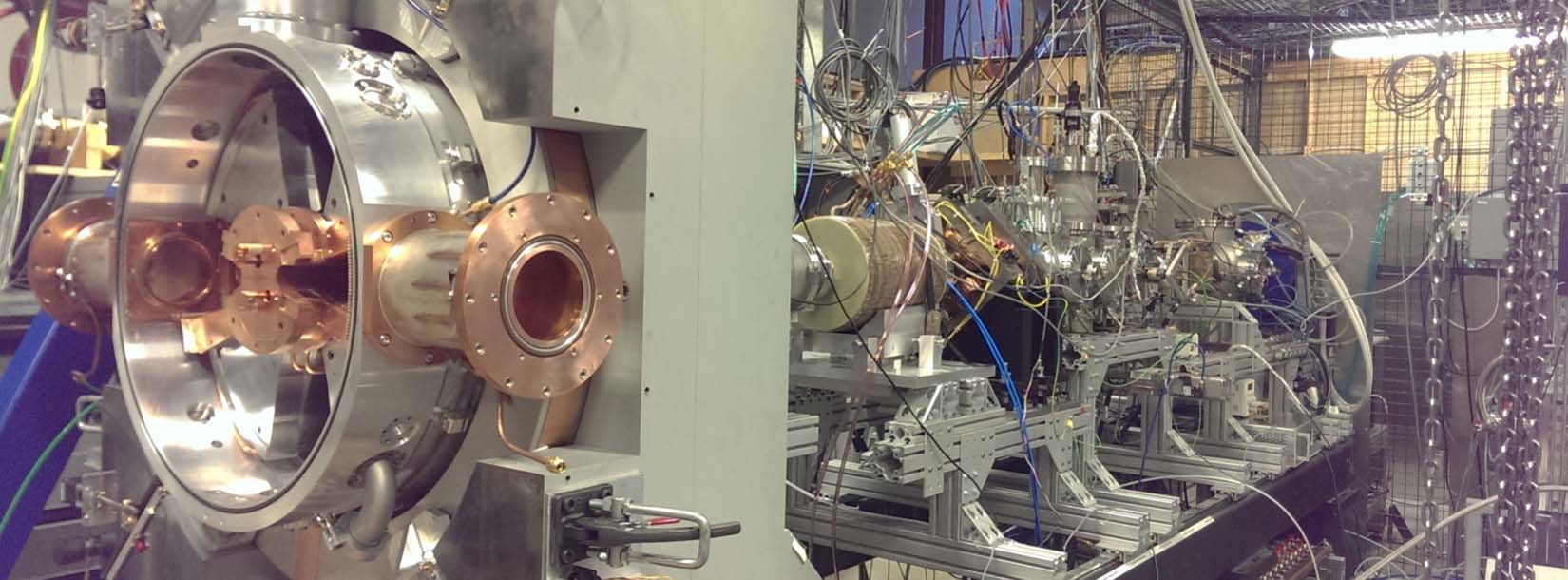
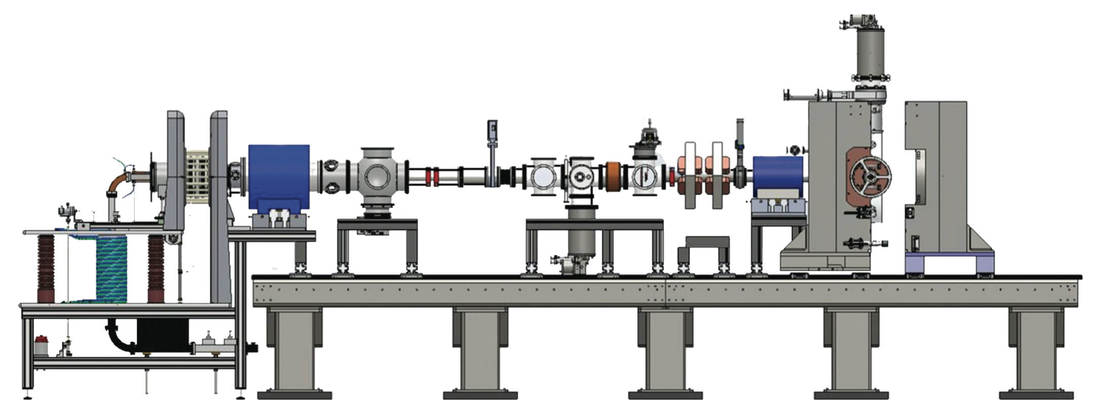
In the summers of 2013 and 2014, we set up a cyclotron test stand a the Best Cyclotron Systems Inc. in Vancouver Canada. Our goal was three-fold: to measure the amount of H2+ which the Veristile Ion Source (VIS) could produce, to test the transport efficiency through a large spiral inflector, and to capture some beam into the test cyclotron. Our beamline consisted of the VIS, a low energy beam transport system (LEBT) -- which includes focusing elements and beam diagnosis equipement, and a 1 MeV test cyclotron.
The VIS source was able to produce good currents of H+2 ions(9.0±0.5mA); with the initial (large) plasma chamber the best ratio of H2+/protons was > 40%, obtained at microwave power just above the threshold for stable discharge operation (about 300 watts). This current improved to 12.2 ± 0.6 mA using a smaller (2.5 cm dis x 10 cm long) plasma chamber, and at the same time the H2+ /proton ratio improved to > 50%. Modeling and systematic measurements had suggested that smaller chambers would improve H2+ production, due to wall-recombination effects, and this was indeed borne out by experiment. We expect further optimization of the chamber shape to yield yet improved performance.
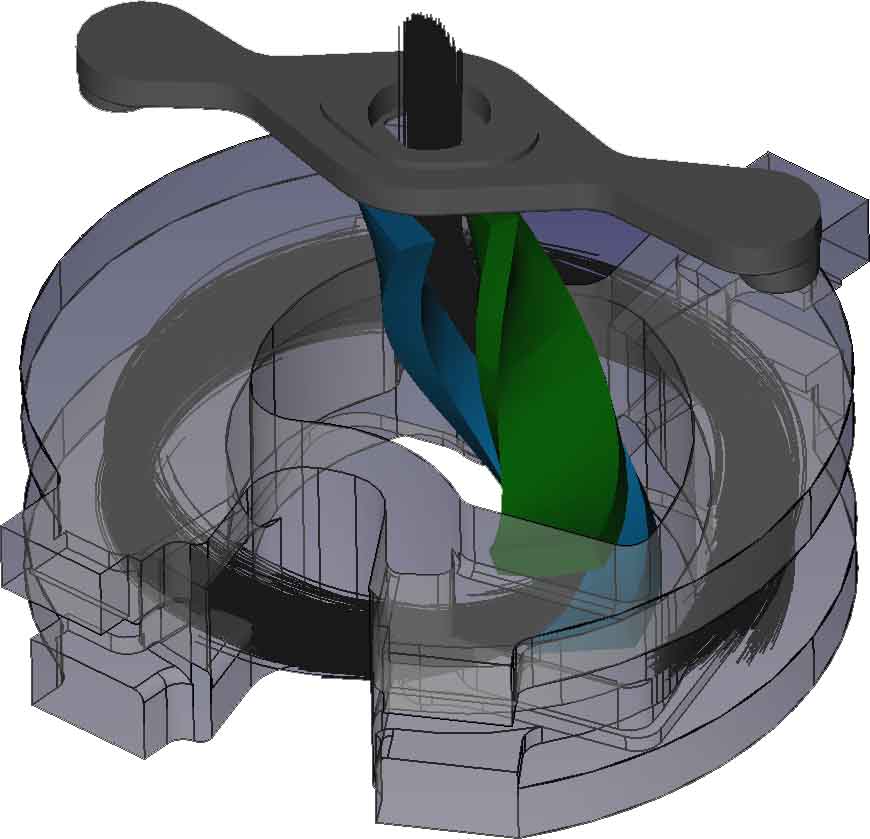
A key result of our experiments has been the validation of the spiral inflector design for these more rigid, high current beams. It should be noted here that the final IsoDAR design will be a further improvement over the BCS test stand model as it will operate in combination with 4 RF cavities in 4th harmonic mode. This will allow for better vertical focusing and will improve the injection efficiency of the cyclotron.
Beam was captured and accelerated through 4 turns in the cyclotron, however with very high losses because of inadequate RF accelerating voltage. The problem of sparking across a critical insulator which limited the highest voltage obtainable, and unfortunately this insulator could not be redesigned before the end of our experimental run. However VectorFields OPERA simulations did provide qualitative fits to the data observed.
From the Vancouver tests, we have identified two possible improvements to the LEBT:
Until an experiment demonstrating injection of H2+ into a cyclotron using the RFQ is performed, the RFQ is considered an alternative design and the conventional LEBT will be the primary design.
We are also focusing on the development a new multi-cusp ion source. At this point, we expect the multicusp ion source to deliver the better performance, but with the drawback of limited lifetime. We have a switching magnet and thus could envision the use of two sources to essentially double the lifetime. This is our primary design.